|
|
Our Home Water Power Site
|
|
|
|
|
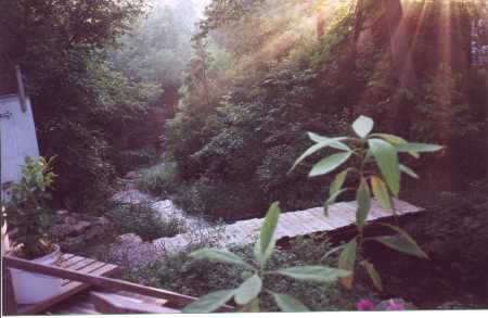
In the mystical beauty just outside our back door is our home waterpower site. In the 1800's, because it is located at the main intersection of the village, this was the most prominent (although it was certainly not the largest) watermill site in the village.
At one time there were over fifteen mills on the two headwater streams of the Pine River in the village. The water would be captured at one dam and then released down to another. There was more water year round in those days because the forests held snow to melt for much longer seasons, and truly there was much more snow in the winters.
|
|
|
|
|
|
|
|
|
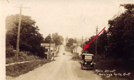
This is how the village still looks, which is probably about 80 years after this picture taken. Standing at this spot one would see that most of the buildings in the picture are still standing and those are still the only buildings they would see. The only difference I can see is that the street has been paved and the building where the arrow points is where our house is now. The big building behind it was a hotel. |
|
|
|
|
|
|
|
|
|
| |
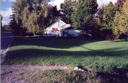
This is our house today at the bottom of the same hill and still looking back up the hill. In the forefront of the picture is the bank of the stream that comes from under the house across the road and runs around behind our house. The big building that was the hotel is barely visible through the big weeping willow in our front yard. There were also two other hotels and a couple of general stores across the street, the buildings for which are still there.
|
|
|
|
|
|
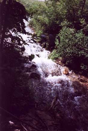
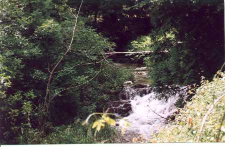
This is where the water starts downward on our property - as it turns away from the road. We have a little over a ten foot drop to the bottom of the dam at the other end of the property which was the first mill on the stream. This stream flows year round and the volume is fairly constant although once or twice I have seen three or four times the volume during times of extended rain.
|
|
|
|
|
|
|
|
 |
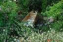
Standing on the first bridge behind our house and looking downstream towards the second.
|
|
|
|
|
This is what is left of the old dam at the other end of our property. This doesn't make any difference to our new design using the pipe because all we need is the drop - not the water behind the dam. The dam is now only half as high as it was when we bought the house a quarter century ago and it used to be higher still. In the olden days they would allow the water to fill up behind the dam, a process that I would estimate to take between 45 minutes and a hour and fifteen minutes and then there would be power to mechanically run the saw to cut planks for maybe twenty minutes. As the water went down the saw would get slower and slower and then they would eventually stop and let the water build up again. The dam is now all silted in. I had it cleaned out about twenty five years ago but it silts back in, in about five years.
|
|
|
|
|
|
|
|
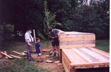 |
Here you see myself and my grandson helping my son build a cedar crib to capture the water up near the road.
|
|
|
|
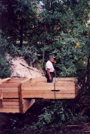 |
Here is Capt. Bill in command of the little ark as we sail it into the stream. Bill started as assistant foreman over 20 years ago in the building of Ark Two. Since Percy passed on he has been our foreman.
|
|
|
|
 |
This was the cedar box down in the stream. We planned to pack dirt along one side and to provide a fish ladder on the other. The box itself strained out sand so that it would not go down the pipe and into our power generating system. |
|
|
|
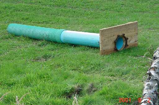 |
On the back of the cedar box we would have attached this pipe.
|
|
|
|
|
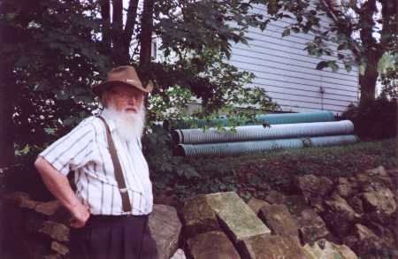
And then these new pipes would have been buried in the bottom of the stream so as to not destroy the scenic view. In the face of pressing need for energy after a nuclear war we may not have for a long time the luxury of burying them. Originally the stream was a mosquito marsh but years ago I had it lined with giant boulders and put the bridges from both sides of our property across it. Even this would not be permitted today under current government bureaucracy.
|
|
|
|
|
|
|
|
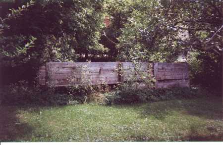 |
And this is the cedar box back up on the bank after ENFORCEMENT (that is what the 10 inch high letters say on the front of their truck) made us take it back out.
|
|
I have told you this whole story so that you can know the degree that we have worked on this system. We think we have a concept that will work exceptionally well on lowhead water sources. In the following paragraphs I will explain the technological concept of the system so that hopefully others will be able to apply the principles elsewhere.
Every system is unique
Every waterpowered electrical generation system has to be tailor made to:
the volume of flow
the height of the head
the layout of the land
the climate
the generation goals
the materials available
environmental concerns
There are many sub-subjects consideration such as:
dam construction
flume construction
power house construction
transmission line construction
power distribution
power sharing or restrictions
Varieties of Approaches
There are a variety of technological approaches to meeting each of the requirements but it will be of little benefit to list all that is available today when the real issues will be what is available at the time of nuclear recovery construction when one will have to make do with what they can find then. A concrete dam might be better than an earthen one but you may have to make do with an earthen or even log and stone dam. A higher dam might be better than a lower. But you will have to do what you can safely do with the materials that you have.
Waterwheels
In the olden days the main mechanical power technology used was the water wheel. These fell into two categories of the overshot wheel and the undershot wheel. The advantage of the overshot is that it can be made of "buckets" and the weight of the water as it goes down will greatly add to the wheel's momentum. The larger the wheel the more sustained momentum. The disadvantage of the overshot wheel is that its height takes away from the available head. However, if the head is very high, then this may make little difference. Unfortunately most situations will have the problem of a low head rather than the advantage of a high head.
The undershot wheel only captures the water flowing through and therefore does not gain from the benefit of the weight of the water but is more suitable to lowhead situations. There is actually a third choice, not often seen, and that is the sideshot wheel in which the wheel lies on its side at the lowest level and the water is directed from the side by a nozzel towards the propellers. In this configuration it is possible that the wheel can still be quite large. Indeed this is the design that we have chosen for the house system at the smaller falls.
Turbines
For those who go out and buy waterpower generating systems - the preferred systems are usually turbines. These are finned devices (of a variety of types) some that fit directly into the flume. The design specific to a system needs to meet two factors - the diameter of the pipe and and the volume of the water. The volume and diameter will determine the speed of the turbine. For seventy-five thousand dollars, one engineering firm offered to run their computer program for us that would give an optimal design for a turbine on our smaller stream. We declined. But, you can see how technical this could get.
The main designs of small capacity turbines are called the Pelton, Turgo, Francis and Crossflow. Each have their advantages in certain situations and disadvantages in others. However, this is not a proper subject for a web page dealing with the development of systems in a nuclear recovery situation. Those who have the luxury of building a system ahead of time, when they have the option of obtaining various designs, can research the sources elsewhere on the web.
A Unique Approach for use in
Post Nuclear Recovery
Days of touring salvage yards to see what may be applied found that there are often large paddle devices that were industrial air blowers, churning devices, or what were in effect large low volume pumps. By directing the water through nozzels at these paddles or blades we feel that some sustained momentum may be achieved. One of the major considerations is to design the water exit in such a manner that you are not losing the energy in pushing the water out. The idea is not to move the water (although that may have been the original idea behind the device) but instead for our purpose the idea is to get as much energy as possible from the force of the water. For this reason one good approach may be to simply lay the wheel and cabinet on its side (although it was not originally designed to work that way) and cut some holes in the cabinet so that the water will just fall away.
Scientific Principle
There are two considerations or concepts that one must keep in mind with any waterwheel and these are momentum and torque.
Momentum / RPM
Momentum is the speed at which the wheel moves. We measure it in RPM (Revolutions Per Minute). Some people have trouble in thinking in RPM, so I will try to help clarify the concept. The earth has a relatively low rpm. Not even ONE rpm. Not even one revolution per hour. It takes it 24 hours to make one turn. Admittedly - its outer edge is moving at hundreds of miles per hour. And if you think that is big and slow - think of the galaxy. Billions of years to make a revolution although again - its outer edge is moving at thousands of miles per hour. It is just a long way around. Generators (like those on a car) generally need 1800 rpm or more. That is to say they need to make 1800 revolutions per minute. An average speed for our low rpm generators is 400 rpm but to help think this through let us say that it was 300 rpm. At 300 revolutions per minute it is making 5 revolutions every second. (60 seconds in a minute times 5 revolutions per second equals 300 rpm (revolutions per minute). Not terribly fast. Something you can see.
Torque
Torque is a function of BOTH speed and mass. Think of the earth in our example above. While it is moving relatively slowly because of its mass -
think of what it would take to stop it. Or the galaxy. The Mass!! Billions upon billions of stars and planets. Big - slow - although the outer edge is moving at thousands of miles per hour - but the torque!! It may seem that rotation speed is a function of size - because for example the electrons of atoms spin VERY fast - so fast that we speak of their rpm as frequency. But torque is a function of both speed and mass. A very large body with low speed has lots of torque. So does a small body with lots of speed. But it is the total combined that gives the ultimate measure of torque. Closer to the size of things we observe everyday let us take the example of a big truck wheel that is moving very fast. Once it is up to speed even if then just freewheeling it would take a lot of energy to stop it - because it is big and heavy and moving fast.
Conversion of the Mass component of Torque to Momentum
Torque is made up both momentum and mass. The momentum/speed component of torque can be converted to mass/weight and the mass/weight component of torque can be converted to speed/momentum. Let us first look at converting the mass component of torque to momentum. We can do this through the use of gears or pulleys. Chain driven gears may work better around water than belt/pulley driven devices but the principle remains the same. We go from a larger wheel with its torque consisting of a large slow moving mass/weight to a smaller wheel which will then turn faster.
Picture the belt/chain around the large wheel that is turning slowly and then the belt/chain extending down to the smaller wheel which then must turn quickly to keep up with the speed of the belt. The shaft of the smaller wheel can have on it another somewhat larger wheel that will then be turning at the same faster speed of the smaller wheel and a chain/belt from that larger wheel to still another smaller wheel on another shaft will repeat the principle with this second smaller wheel going faster still. The process can be repeated a number of times so that while the first wheel may have been turning only a few revolutions per minute - we can arrive at a wheel turning thousands of revolutions per minute - if that is our goal and PROVIDING that the first wheel has enough torque (combination of weight/mass and energy/momentum) to sustain the drag of the added gears or pulleys.
The reverse principles can be used to make a fast moving small wheel turn more slowly a large wheel, but it is more likely that in our application we are going to need to use the method given in the example. Adding the weight or drag of the belt/chain slows down the big wheel and our problem is that usually we cannot make it go fast enough to overcome the drag that we wish to add to it.
Using a slow waterwheel to run a faster generator
In our above horizontal waterwheel we would have the water hitting the paddles of the the wheel from several sides of the wheel. As an analogy, think of the old playground merry-go-round. Children stand around the outside adding to the speed of the spin. Each one pushing on a bar as it goes by. Eventually they cannot push very much on the merry-go-round because it comes by too fast for them to get a hold on it. Each child is not adding much energy to the wheel as it goes past. Each child's energy potential is being wasted.
The same thing happens when our waterwheel is coming past the nozzels too fast. The water from the nozzel does not get to hit the blade for very long - so its energy is wasted. The thing to do is to slow down the wheel. We do this by putting more weight on it. Now more energy will go into the wheel at each nozzel. With the merry-go-round there would be more children on the wheel and those standing and pushing would have longer to push the bar in front of them. We use the same principle to capture more of the speed of the water in our nozzels and to change it to torque in the waterwheel. We simply add weight and that slows down the wheel and allows us to capture more energy from the speed and force of the water.
A merry-go-round with few children on it is much easier to stop than another one moving at the same speed with many children on it. That is the effect of mass on torque. A body in motion tends to stay in motion and the heavier the body in motion - the harder it is to stop. This is one of the reasons why we like heavy flywheels in our system.
The Drawback to Flywheels
The DRAWBACK to flywheels is that there is ALWAYS a loss of energy in conversion so ideally we would instead like for our initial wheel to be moving at the end desired speed with the maximum torque it that can master. Because it is difficult, with low head sources, to actually get up to 1800 rpm it is more optimal to use low rpm generators and so consequently our target is more in the area of 400 rpm. The question then becomes one of how much torque (mass/weight - moving at 400 rpm) can we develop from our blade/paddle and nozzel system. We are not wanting to just keep adding weight to the wheel until it slows down to 400 rpm because while it would have good momentum and torque - that is to say it would be difficult to slow down - that weight we added would be just dead weight and the energy (work) that we were using to move it around would be just useless work.
The weight that we want to add as directly as we can to the waterwheel is the weight or energy requirement of turning our generator at 400 rpm. If the waterwheel has the capacity to turn our generator at twice that speed then that is great because we can then let it turn two generators at the same time and we will get twice the electrical output. Conversely, if our waterwheel while initially turning at 400 rpm slows down to half that speed when we add the weight of turning the generator - then perhaps we need a smaller generator or two waterwheels to turn the generator, or a bigger faster waterwheel, or some other combination.
Waterwheel Variables
There are many variables that we can perhaps adjust. The size and weight of the waterwheel, the gear/pulley ratio of the drive to the generator, the number, angle and closeness of the nozzels shooting water onto the paddle/blades and the volume and speed of the water coming through the nozzels. There will undoubtedly be much skill involved in maximizing the adjustments. But no matter - with some reasonable application of the principles involved and some reasonable resources as to waterhead and volume and the components I have described - one should be able to produce some amount of electrical energy. Hopefully an amount that will make the effort worthwhile.
I would liked to have carried this idea beyond theory, but The Powers That Be would not let me proceed with my experiments. We will have to make do with what we have available but we would particularly have liked to have worked further on the design of the nozzels - an art in itself.
|
|
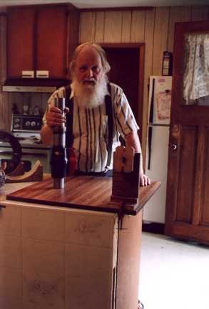 |
Nozzels I called around North America and talked with a number of nozzel design engineers and went and visited a couple. Basically what we concluded was that the antique fire hose nozzel of old was the best that we could do. It is long tapered and pointy (at least on the inside). This is somewhat difficult to machine but that is the ideal. One starts with a long bar of steel, (or plastic - if that is what you have and can handle), cut it up into appropriate nozzel lengths and then mill down into the inside.
We have bought all the components for the number (twenty-four) that we think that we will need at our two sites. Connectors, valves, makings for the nozzels, and lots of hose.
In the picture I am holding one of the assembled nozzels. We have also gone ahead and put in place the power house and have acquired the big batteries for the system but we have gone as far as the government will permit us to go.
|
|
As I have said - it would have been much better to get our home waterpower system working ahead of time and to prove out the design - but we have gone about as far as the government will permit us to go. We are also considering an altogether different approach for the large waterfall and that is a large pump which we would use as a turbine. But that subject is covered in its own place.