Fig. 1. Section through the upper part of a doorway, showing operation of a
KAP. (ORNL-DWG 66-12320A) 
Fig. 2. KAP in doorway (with flaps open during its return stroke). (ORNL-DWG
66-12319A) 
| MENU: HOME » SURVIVAL » Index of States |
I. THE NEED FOR SHELTER AIR PUMPS
In warm weather, large volumes of outside air MUST be pumped through most fallout or blast shelters if they are crowded and occupied for a day or more. Otherwise, the shelter occupants' body heat and water vapor will raise the temperature-humidity conditions to DANGEROUSLY high levels. If adequate volumes of outdoor air are pumped through typical belowground shelters in hot weather, many times the number of persons could survive the heat than otherwise could survive in these same shelters without adequate forced ventilation. Even in cold weather, about 3 cubic feet per minute (3 cfm) of outdoor air usually should be pumped through shelters, primarily to keep the carbon dioxide exhaled by shelter occupants from rising to harmful concentrations.
The KAP (Kearny Air Pump) is a practical, do- it-yourself device for pumping adequate volumes of cooling air through shelters with minimum work. The following instructions have been improved repeatedly after being used by dozens of small groups to build KAPs including families, pairs of housewives, and children. None of these inexpert builders had previously heard of this kind of pump, yet almost all groups succeeded in making one in less than 4 hours after assembling the materials. Their successes prove that almost anyone, if given these detailed and thoroughly tested instructions, can build a serviceable, large-volume air pump of this simple type, using only materials and tools found in most American homes.
If possible, build a KAP large enough to pump through your shelter at least 40 cubic feet per minute (40 cfm) of outdoor air for each shelter occupant. If 40 cfm of outdoor air is pumped through a shelter and distributed within it as specified below, even under heat-wave conditions the effective temperature of the shelter air will not be more than 20 F higher than the effective temperature outdoors. (The effective temperature is a measure of air's effects on people due to its heat, humidity, and velocity.) The 36-inch-high by 29-inch-wide KAP described in these instructions, if used as specified, will pump at least 1000 cfm of outside air through a shelter that has the airflow characteristics outlined in these instructions.
If more than 25 persons might be expected to occupy a shelter during hot weather, then it is advisable to build a larger KAP. The 72-inch-high by 29-inch-wide model described can pump between 4000 and 5000 cfm.
To maintain tolerable temperature-humidity conditions for people in your shelter during hot weather, you must:
° Pump enough outdoor air all the way through the shelter (40 cfm for each occupant in very hot, humid weather).
° Distribute the air evenly within the shelter. If the KAP that pumps air through the shelter does not create air movement that can be felt in all parts of the shelter in hot weather, one or more additional KAPs will be needed to circulate the air and gently fan the occupants.
° Encourage the shelter occupants to wear as little clothing as practical when they are hot. (Sweat evaporates and cools best on bare skin.)
Book Page: 194
° Supply the occupants with adequate water and salt. For prolonged shelter occupancy under heat- wave conditions in a hot part of the country, about 4 quarts of drinking water and 1/3 ounce (1 tablespoon) of salt per person are required every 24 hours, including salt in food that is eaten. Normal American meals supply about 1/4 ounce of salt daily. Salt taken in addition to that in food should be dissolved in the drinking water.
° Pump outdoor air through your shelter day and night in warm weather, so that both the occupants and the shelter are cooled off at night.
Almost all of the danger from fallout is caused by radiation from visible fallout particles of heavy, sand- like or flaky material. The air does not become radioactive due to the radiation continuously given off by fallout particles.
The visible fallout particles rapidly "fall out" of slow moving air. The air that a KAP pumps through a shelter moves at a low speed and could carry into the shelter only a very small fraction of the fallout particles that cause the radiation hazard outside. This fraction, usually not dangerous, can be further reduced if occupants take the simple precautions described in these instructions.
CAUTION
Before anyone starts to build this unusual type of air pump, ALL WORKERS SHOULD READ THESE INSTRUCTIONS AT LEAST UP TO SECTION V, INSTALLATION. Otherwise mistakes may be made and work may be divided inefficiently.
When getting ready to build this pump, all workers should spend the first half-hour studying these instructions and getting organized. Then, after materials are assembled, two inexperienced persons working together should be able to complete the 3-foot model described in the following pages in less than 4 hours. To speed up completion, divide the work; for example, one person can start making the flaps while another begins work on the pump frame.
II. HOW A KAP WORKS
As can be seen in Figs. 1 and 2, a KAP operates by being swung like a pendulum. It is hinged at the top of its swinging frame. When this air pump is pulled by a cord as illustrated, its flaps are closed by air pressure and it pushes air in front of it and "sucks"air in back of it. Thus a KAP pumps air through the opening in which it swings. This is the power stroke. During its power stroke, the pump's flaps are closed against its flap-stop wires or strings, which are fastened across the face of the frame.
Fig. 1. Section through the upper part of a doorway, showing operation of a
KAP. (ORNL-DWG 66-12320A)
Fig. 2. KAP in doorway (with flaps open during its return stroke). (ORNL-DWG
66-12319A)
Book Page: 195
When a KAP swings freely back as a pendulum on its return stroke, all its flaps are opened by air pressure. The pumped air stream continues to flow in the direction in which it has been accelerated by the power stroke, while the pump itself swings in the opposite direction (see Fig. 2). Thus the flaps are one-way valves that operate to force air to flow in one direction, where desired.
The KAP can be used: (1) to supply outdoor air to a shelter, (2) to distribute air within a shelter, and/or to fan the occupants.
1. To force outdoor air through a shelter, an air- supply KAP usually is operated as an air-intake pump by pulling it with a cord (see Fig. 1). (Only rarely is it necessary to operate a KAP as an air- exhaust pump by pushing it with a pole, as described in the last section of these instructions.)
2. To distribute air within a shelter and/or to fan the occupants, air-distribution KAPs may be hung overhead and operated as described later.
III. INSTRUCTIONS FOR BUILDING A KAP
In this section, instructions are given for making a KAP 36 inches high and 29 inches wide, to operate efficiently when swinging in a typical home basement doorway 30 inches wide. If your doorway or other ventilation opening is narrower or wider than 30 inches, you should make your KAP 1 inch narrower than the narrowest opening in which you plan to install it. Regardless of the size of the KAP you plan to build, first study the instructions for making the 36 X 29-inch model.
In Section VII you will find brief instructions for making a narrower and even simpler KAP, one more suitable for the narrow openings of small trench shelters and other small expedient shelters. Section VIII covers large KAPs, for large shelters.
A. Materials Needed for a KAP 36 inches High by 29 inches Wide
The preferred material is listed as first (1st) choice, and the less-preferred materials are listed as (2nd), (3rd), and (4th) choices. It is best to assemble, spread out, and check all your materials before beginning to build.
1. The pump frame and its fixed support:
° Boards for the frame:
(1st) 22 ft of 1 X 2-in. boards. (A nominal 1 X 2-in. board actually measures about 3/4 x l-3/4 in., but the usual, nominal dimensions will be given throughout these instructions.) Also, 6 ft of 1 X 1-in. boards. Soft wood is better.
(2nd) Boards of the same length that have approximately the same dimensions as 1 X 2- in. and 1 X 1-in. lumber.
(3rd) Straight sticks or metal strips that can be cut and fitted to make a flat-faced KAP frame.
° Hinges: (1st) Door or cabinet butt-hinges; (2nd) metal strap-hinges; (3rd) improvised hinges made of leather, woven straps, cords, or 4 eyescrews which can be joined to make 2 hinges. (Screws are best for attaching hinges. If nails are used, they should go through the board and their ends should be bent over and clinched flattened against the surface of the board.)
° A board for the fixed horizontal support: (1st) A 1 X 4-in. board that is at least 1 ft longer than the width of the opening in which you plan to swing your pump; (2nd) A wider board.
° Small nails (at least 24): (1st) No. 6 box nails, about 1/2 in. longer than the thickness of the two boards, so their pointed ends can be bent over and clinched); (2nd) other small nails.
2. The flaps (See Figs. 1, 2, 6, 7, and 8):
° Plastic film or other very light, flexible material -- 12 square feet in pieces that can be cut into 9 rectangular strips, each 30 X 5-1/2 in.: (1st) polyethylene film 3 or 4 mils thick (3 or 4 one-thousandths of an inch); (2nd) 2-mil polyethylene from large trash bags; (3rd) tough paper.
° Pressure-sensitive waterproof tape, enough to make 30 ft of tape 3/4 in. to 1 in. wide, for securing the hem-tunnels of the flaps: (1st) cloth duct tape (silver tape); (2nd) glass tape; (3rd) scotch tape; (4th) freezer or masking tape, or sew the hem tunnels. (Do not use a tape that stretches: it may shrink afterward and cause the flaps to wrinkle.)
3. The flap pivot-wires:
(1st) 30 ft of smooth wire at least as heavy and springy as coat hanger wire, that can be made into very straight pieces each 29 in. long (nine all-wire coat hangers will supply enough); (2nd) 35 ft of somewhat thinner wire, including light, flexible insulated wire; (3rd) 35 ft of smooth string, preferably nylon string about the diameter of coat hanger wire.
Book Page: 196
4. The pull cord:
° (1st) At least 10 ft of cord; (2nd) strong string; (3rd) flexible, light wire.
5. The flap-stops:
° (1st) 150 ft of light string; (2nd) 150 ft of light, smooth wire; (3rd) 150 ft of very strong thread; (4th) 600 ft of ordinary thread, to provide 4 threads for each stop-flap.
° (1st) 90 tacks (not thumbtacks); (2nd) 90 small nails. (Tacks or nails are desirable but not essential, since the flap-stops can be tied to the frame.)
B. Tools
A hammer, saw, wirecutter pliers, screwdriver, scissors, knife, yardstick, and pencil are desirable. However, only a strong, sharp knife is essential for making some models.
C. Building a KAP 36 inches High by 29 inches Wide
A 36 X 29-in. KAP is most effective if operated in an air-intake or exhaust opening about 40 in. high and 30 in. wide. (If your shelter might have more than 25 occupants in hot weather, read all these instructions so you will understand how to build a larger pump, briefly described in Section VIII.)
NOTE THAT THE WIDTHS AND THICKNESSES OF ALL FRAME PIECES ARE EXAGGERATED IN ALL ILLUSTRATIONS.
1. The frame
a. Cut two pieces of 1 X 2-in. boards, each 36 in. long, and two pieces of 1
X 2-in. boards, each 29 in. long; then nail them together (see Fig. 3). Use
nails that do not split the wood, preferably long enough to go through the
boards and stick out about 1/2 in. on the other side. (To nail in this manner,
first put blocks under the frame so that the nail points will not strike the
floor.) Bend over nail points which go through.
Next, cut and nail to
the frame a piece of 1 X 1-in. lumber 36 in. long, for a center vertical brace.
(If you lack time to make or to find a 1 X 1-in. board, use a 1 X 2-in. board.)
Figure 3 shows the back side of the frame; the flap valves will be attached on
the front (the opposite) side.
Fig. 3. KAP frame (looking at the back side of the frame). ORNL
71-7003 
b. To make the front side smooth and flat so that the flaps will close
tightly, fill in the spaces as follows: Cut two pieces of 1 X 2-in. boards long
enough to fill in the spaces on top of the 36-in. sides of the frame between the
top and bottom horizontal boards, and nail these filler boards in place. Do the
same thing with a 1 X 1-in. board (or a board the size of that used for the
center brace) as a filler board for the center brace (see Fig. 4).
If the
frame is made of only one thickness of board 3/4 in. to 1 in. thick, it will not
be sufficiently heavy to swing back far enough on its free-swinging return
stroke.
Book Page: 197
2. The hinges
Ordinary door butt-hinges are best. So that the pump can swing past the horizontal position, the hinges should be screwed onto the front of the frame, at its top, in the positions shown in Fig. 4. (Pick one of the 29-in. boards and call it the top.) If you do not have a drill for drilling a screw hole, you can make a hole by driving a nail and then pulling it out. Screw the screw' into the nail hole.
Fig. 4. Completing the frame. ORNL- DWG 66-12322A 
3. The pivot-wires and flaps
a. Make 9 flap pivot-wires. If you have smooth, straight wire as springy and thick as coat hanger wire, use it to make nine 29-in.-long straight lengths of wire. If not, use wire from all-wire coat hangers or use strings. First cut off all of the hook portion of each coat hanger, including the twisted part. If you have only ordinary pliers, use the cutter to "bite" the wire all around; it will break at this point if bent there. Next, straighten each wire carefully. Straighten all the bends so that each wire is straight within 1/4 in., as compared to a straight line. Proper straightening takes 1 to 5 minutes per wire. To straighten, repeatedly grasp the bent part of the wire with pliers in slightly different spots, each time bending the wire a little with your other hand. Then cut each wire to a 29-in. length. Finally, bend no more than 1/2 in. of each end at a right angle and in the same plane that is, in directions so that all parts of the bent wire will lie flat against a smooth surface. The bent ends are for secure attachment later (see Fig. 8).
b. Make 9 polyethylene flaps that will be the hinged valves of the KAP. First cut 9 strips, making each strip 30 in. long by 5-1/2 in. wide (see Fig. 5). To cut plastic flaps quickly and accurately, cut a long strip of plastic 30 in. wide. Then cut off a flap in this way: (1) draw a cutting guideline on a wide board 5-1/2 in. from an edge; (2) place the 30-in.-wide plastic strip so that it lies on this board, with one of the strip's side edges just reaching the edge of the board; (3) place a second board over the plastic on the first board, with a straight edge of this second upper board over the guideline on the lower board; and finally (4) cut off a flap by running a sharp knife along the straight edge of the upper board.
Fig. 5. ORNL DWG 71-7004A 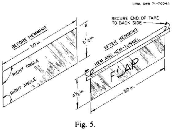
Book Page: 198
To form a hem along one of the 30-in. sides of a 5-1/2 X 30-in. rectangular
strip, fold in a 1-in. hem. This makes the finished flap 4-1/2 in.
wide.
To hold the folded hem while taping it, paper clips or another pair
of hands are helpful. For each hem, use two pieces of pressure-sensitive tape,
each about 1 in. wide and 16 in. long. Or make the hem by sewing it very close
to the cut edge to form a hem-tunnel (see Fig. 5).
After the hem has been
made, cut a notch with scissors in each hemmed corner of the flap (Figs. 6 and
8). Avoid cutting the tape holding the hem. Each notch should extend downward
about 1/2 in. and should extend horizontally from the outer edge of the flap to
1/4 in. inside the inner side of the frame, when the flap is positioned on the
frames as shown in Fig. 6.
Fig. 6. Sizes of notches in flaps. ORNL-DWG 66-12324 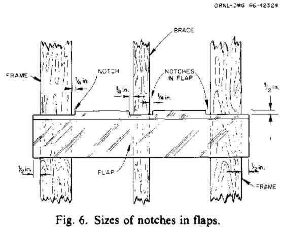
Also cut a notch in the center of the flap (along the hem line) extending 1/2 in. downward and extending horizontally 1/4 in. beyond each of the two sides of the vertical brace (see Fig. 6). The notch MUST be wider than the brace. [However, if you are building a pump using wire netting for flap-stops (see Fig. 13), then do NOT cut a notch in the center of each flap.]/P>
c. Take the 9 pieces of straightened wire and insert one of them into and through the hem-tunnel of each flap, like a curtain rod running through the hem of a curtain. Check to see that each flap swings freely on its pivot-wire, as illustrated by Fig. 7. Also see Fig. 8.
Fig. 7. End view. ORNL-DWG 66-12325 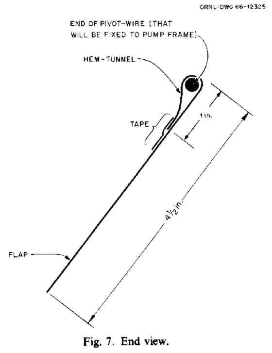
Fig. 8. Flap. ORNL DWG 71-7005A 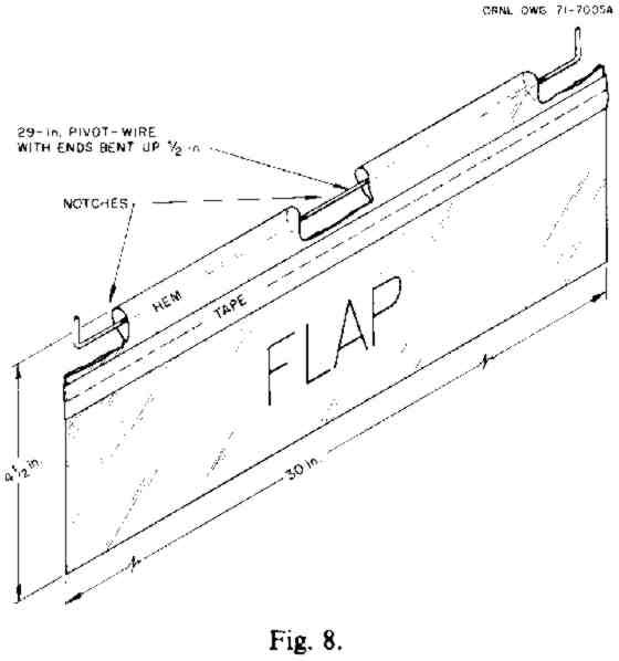
Book Page: 199
Ruler for Marking Positions of Flap Pivot - Wires and Flap-Stops 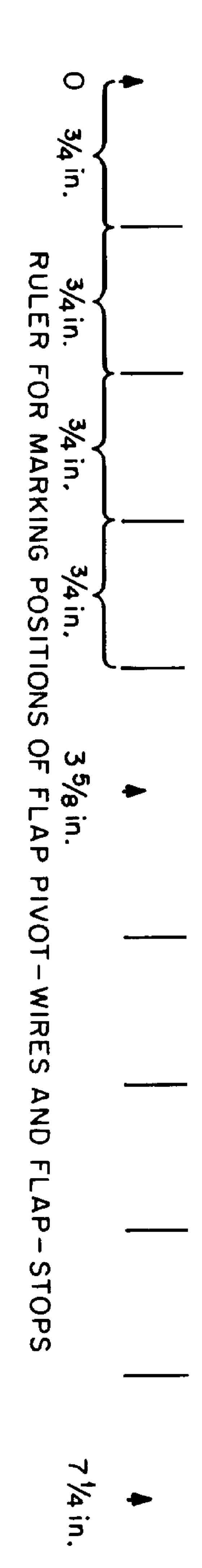
d. Put aside the flaps and their pivot-wires for use after you have attached the flap-stops and the hinges to the frame, as described below.
e. Using the ruler printed on the edge of this page, mark the positions of each pivot-wire (the arrowheads numbered 0, 3-5/8, 7-1/4 in.) and the position of each flap-stop (the four marks between each pair of numbered arrowheads on this ruler). All of these positions should be marked both on the vertical sides of the 36-in.-long boards of the frame and on the vertical brace. Mark the position of the uppermost pivot-wire (the "0" arrowhead on this ruler) 1/4 in. below the top board to which the hinges have been attached (see Figs. 9 and 10).
Fig. 9. (Frame 3/4 View) ORNL DWG 71-7006A 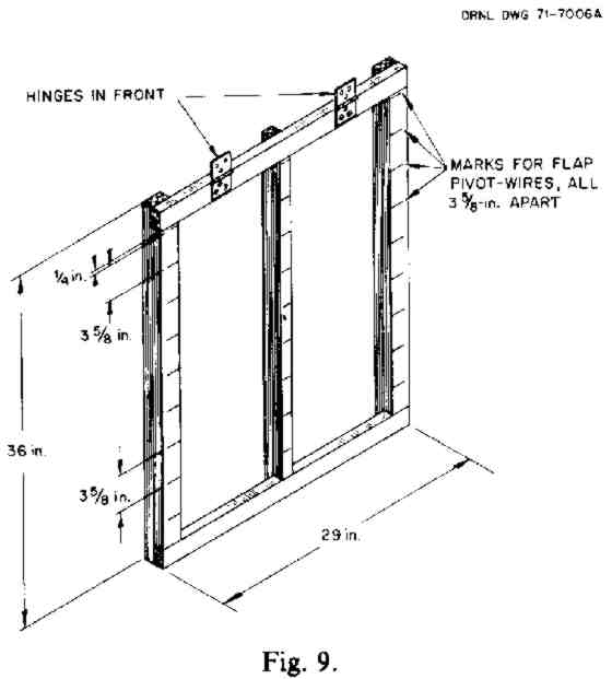
Fig. 10. (Top of Frame Straight on View) ORNL-DWG 66-12328A 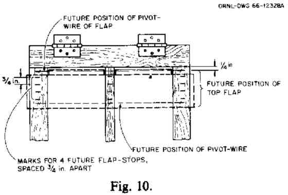
4. The flap-stops
So that the flaps may swing open on only one side of the frame (on its front, or face), you must attach horizontal flap-stops made of strings or wires across the face of the frame. (See Figs. 10 and 11.) Nail or tie four of these flap-stops between the marked points where each pair of the horizontal pivot-wires for the flaps will be placed. Be careful not to connect any flap-stops in such a way that they cross the horizontal open spaces in which you later will attach the flap pivot-wires.
Fig. 11. Positions of pivot-wires and flap-stops. ORNL -DWG
71-7007A 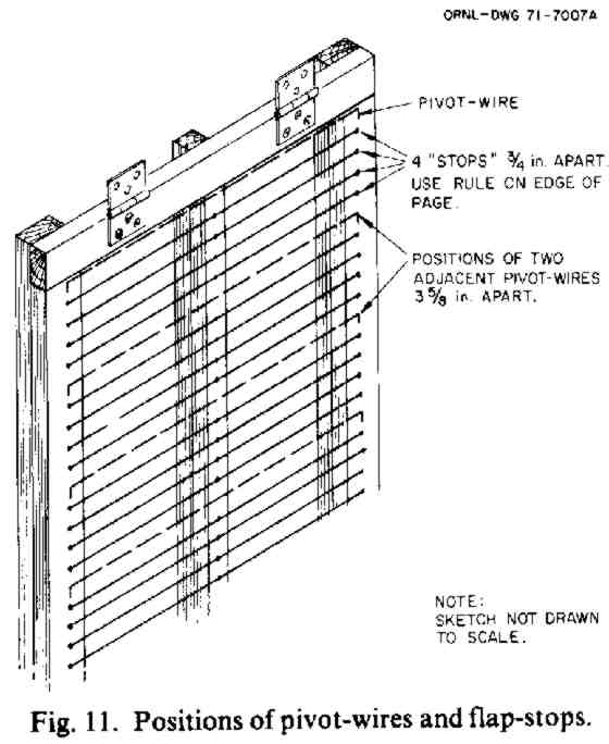
If you have tacks (NOT thumbtacks) or very small nails, drive three in a horizontal line to attach each flap-stop-one in each of the two vertical 36-in. sides of the frame and one in the vertical center brace (see Fig. 11). First, drive all of these horizontal lines of tacks about three-quarters of the way into the boards. Then, to secure the flap-stop string or thin wire quickly to a tack, wind the string around the tack and immediately drive the tack tightly into the frame to grip the string (see Fig. 11).
If you have no tacks or nails, cut notches or slots where the flap-stops are to be attached. Cut these notches in the edges of the vertical sides of the frame and in an edge of the center brace. Next, secure the flap-stops (strings or wires) by tying each one in its notched position. This tying should include wrapping each horizontal flap-stop once around the vertical center brace. The stops should be in line with (in the same plane as) the front of the frame. Do not stretch flap-stops too tightly, or you may bend the frame.
Book Page: 200
5. Final assembly
a. Staple, nail, or tie the 9 flap pivot-wires or pivot-strings (each with
its flap attached) in their positions at the marked 3-5/8 in. spacings. Start
with the lowest flap and work upward (see Fig. 11). Connect each pivot-wire at
both ends to the 36-in. vertical sides of the frame. Also connect it to the
vertical brace. BE CAREFUL TO NAIL THE PIVOT-WIRES ONLY TO THE FRAME AND THE
BRACE. DO NOT NAIL ANY PLASTIC DIRECTLY TO THE WOOD. All flaps must turn
freely on their pivot-wires.
If any flap, when closed, overlaps the flap
below it by more than 1 in.. trim off the excess so that it overlaps by only 1
in.
b. Screw (or nail, if screws are not available) the upper halves of the
hinges onto the horizontal support board on which the KAP will swing. (A
l-in.-thick board is best, 3-1/2 in. wide and at least 12 in. longer than the
width of the doorway or other opening in which this KAP is to be
installed.)
Be careful to attach the hinges in the UNusual,
OUT-OF-LINE POSITION shown in Fig. 12.
CAUTIONS: Do NOT attach a
KAP's hinges directly to the door frame. If you do, the hinges will be torn
loose on its return stroke or on its power stroke.
If you are making a KAP to fit into a rectangular opening, make its frame 4 in. SHORTER than the height of its opening and 1 in. NARROWER than the width of the opening.
c. For this 3-ft model, tie the pull-cord to the center brace about 12-1/2 in. below the hinge line, as shown in Fig. 12. (If you tie it lower, your arm movements will waste energy.) Use small nails or wire to keep the tie end from slipping up or down on the center brace. (For a more durable connection, see Fig. 22.)
Cut a slot in the flap above the connection of the pull-cord to the vertical brace, deep enough so that this flap will close completely when the KAP is being pulled. Tape the end and edges of the slot.
Fig. 12. Hinge is attached so pump can swing 180 degrees. ORNL-DWG
66-12330AR 
IV. MORE RAPID CONSTRUCTION
(Skip this section if you cannot easily get chicken wire and 1/4 in.-thick boards.)
If chicken wire and boards about 1/4 in. thick are available, use the chicken wire for flap-stops. By using these materials, the time required to build a given KAP can be reduced by about 40%. One-inch woven mesh is best. (Hardware cloth has sharp points and is unsatisfactory.)
Figure 13 illustrates how the mesh wire should be stapled to the KAP frame. Next, unless the KAP is wider than 3 ft, the front of the whole frame (except for the center brace) should be covered with thin boards approximately 1/2 in. thick, such as laths. Then the pivot-wires, with their flaps on them, should be stapled onto the 1/4 in.-thick boards. This construction permits the flaps to turn freely in front of the chicken-wire flap-stops.
With this design, the center of each pivot-wire should NOT be connected to the center brace, nor should the center of the flap be notched. However, pivot-wires that are attached this way must be made and held straighter than pivot-wires used with flap-stops made of straight strings or wires.
Book Page: 201
Fig. 13. Flaps attached 1/4 inch in front of chicken wire used for
flap-stops. ORNL-DWG 66-12333A 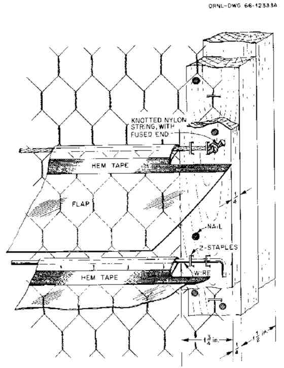
Note in Fig. 13 that each pivot-wire is held firm and straight by 2 staples securing each end. The wire used should be at least as springy as coat hanger wire. If string is used instead of wire, nylon cord about the diameter of coat hanger wire is best for the pivot-strings.
If the KAP is wider than 3 ft, its center vertical brace should also be covered with a 1/4 in.-thick board, and each pivot-wire should be attached to it. Furthermore, the center of each flap should be notched.
V. INSTALLATION AND ACCESSORIES
A. Minimum Open Spaces Around a KAP
To pump its maximum volume, an air-supply KAP with good metal hinges should be installed in its opening so that it swings only about 1/2 in. above the bottom of the opening and only 1/2 in. to 1 in. from the sides of the opening.
B. Adequately Large Air Passageways
When using a KAP as an air-supply pump to force air through a shelter, it is essential to provide a low-resistance air passageway all the way through the shelter structure from an outdoor air-intake opening for outdoor air to a separate air-exhaust opening to the outdoors (see Fig. 14).
Fig. 14. (ORNL-DWG) 66-12331AR2 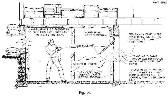
Book Page: 202
A low-resistance air passageway is one that is no smaller incross-sectional area than half the size of the KAP pumping the air. For example, a 36 X 29-in. KAP should have a passageway no smaller than about 3-1/2 sq. ft. An air-supply KAP of this size will force at least 1000 cubic feet per minute (1000 cfm) through a shelter having such openings, if itis installed as illustrated in Fig. 14.
If smaller air passageways or air-exhaust openings are provided, the volume of air pumped will be greatly reduced. For example, if the air-exhaust opening is only l-3/4 sq. ft (1/4 the size of this KAP), then this KAP will pump only about 500 cfm. And if the air-exhaust opening is only a 6 X 6-in. exhaust duct (1/4 sq. ft), then this same 36 X 29-in. KAP will pump only about 50 cubic feet per minute. This would not provide enough outdoor air for more than one shelter occupant in a well-insulated shelter under heat-wave conditions in the hottest humid parts of the United States. In contrast, when the weather is freezing cold and the shelter itself is still cold enough to absorb the heat produced by the shelter occupants, this same 6 X 6-in. exhaust duct and the air-intake doorway will cause about 50 cfm of outdoor air to flow by itself through the shelter without using any pump. The reason: body heat warms the shelter air, and the warm air rises if cold air can flow in to replace it. Under these cold conditions provided the air is distributed evenly throughout the shelter by KAP or otherwise -- 50 cfm is enough outdoor air for about 17 people.
To provide adequately large air passageways for air-supply KAPs used to ventilate shelters in buildings, in addition to opening and closing doors and windows, it may be necessary to build large ducts (as described below). Breaking holes in windows, ceilings, or walls is another way to make large, efficient air passageways.
Figure 15 illustrates how a 3-ft KAP can be used as a combined air-supply and air-distribution pump to adequately ventilate a small underground shelter that has an exhaust opening too small to provide enough ventilation in warm weather. (A similar installation can be used to ventilate a basement room having only one opening, its doorway.) Note how, by installing a divider in the doorway and entryway, the single entryway is converted into a large air-intake duct and a separate, large air-exhaust duct. To obtain the maximum increased volume of fresh outdoor air that can be pumped through the shelter a total of about 1000 cfm for a 36 X 29-in. KAP the divider should extend about 4 ft horizontally into the shelter room, as shown in Fig. 15. The 6 ft at the end of the divider (the almost-horizontal part under the KAP) can be made of plywood, provided it is installed so that it can be taken out of the way in a few seconds.
Fig. 15. Ventilating a shelter when the air- exhaust opening is too
small. ORNL DWG 72-6630 
Book Page: 203
Note how the entry of fallout into a shelter can be minimized by covering the entryway with a "roof" and by forcing the slow-moving entering air to rise over an obstruction (the "wall") before it flows into the shelter. The sand-like fallout particles fall to the ground outside the "wall."
C. Adequate Distribution of Air Within the Shelter
To make sure that each shelter occupant gets a fair share of the outdoor air pumped through the shelter, air distribution KAPs should be used inside most large shelters. These KAPs are used within the shelter, separate from and in addition to air-supply KAPs (see Fig. 16). Air-distribution KAPs can serve in place of both air-distribution ducts and cooling fans. For these purposes, one or more 3-ft-high KAPs hung overhead from the shelter ceiling are usually most practical. If KAPs cannot readily be hung from the ceiling, they can be supported on light frames made of boards or metal, somewhat like those used for a small child's swing.
Fig. 16. The use of air distribution KAPs. ORNL DWG 72-7547 
You should make and use enough KAPs to cause air movement that can be felt in all parts of your shelter. Remember that if KAPs are installed near the floor and the shelter is fully occupied, the occupants' bodies will partially block the pumped airflow more than if the same KAPs were suspended overhead.
As a general rule, for shelters having more than about 20 occupants, provide one 3-ft air-distribution KAP for every 25 occupants. In relatively wide shelters, these interior KAPs should be positioned so that they produce an airflow that circulates around the shelter, preventing the air that is being pumped into the shelter from flowing directly to the exhaust opening. Figure 16 illustrates how four KAPs can be used in this way to distribute the air within a shelter and to fan the 100 occupants of a 1000-sq.-ft shelter room. Avoid positioning an air-distribution KAP so that it pumps air in a direction greater than a right angle turn from the direction of airflow to the location of the KAP.
D. Operation with a Pulley
A small KAP especially one with improvised hinges or one installed at head-height or higher can be pulled most efficiently by running its pull-cord over a pulley or over a greased homemade pulley" such as described in Figs. 17' and 18. A pulley should be hung at approximately the same height as the hinges of the KAP, as illustrated in Fig. 15. To make
.Fig. 17. IMPROVISED "PULLEY" FROM A WIDE-ANGLED FORKED LIMB. ORNL DWG
71-7242 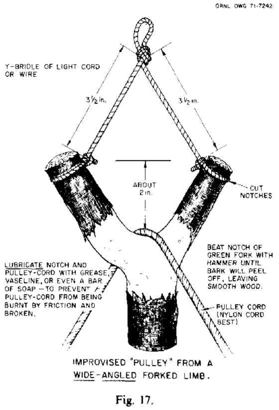
Book Page: 204
Fig. 18. IMPROVISED "PULLEY" ORNL DWG 71-7243 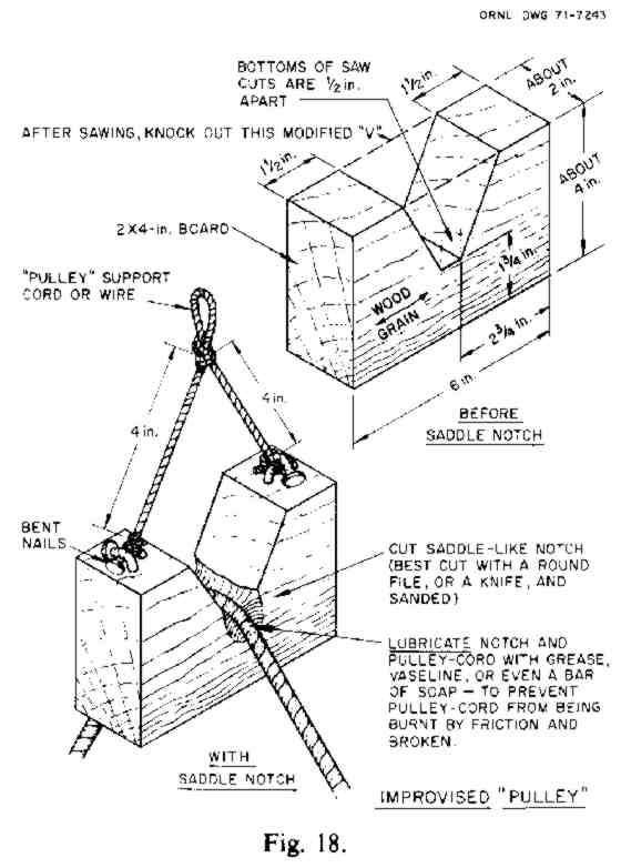
a comfortable hand-hold on which to pull down- ward, tie two or three overhand knots in a strip of cloth on the end of the pull-cord.
(Such a "pulley" can also be used to operate a bail-bucket to remove water or wastes from some shelters, without anyone having to go outside.)
E. Quick-Removal Brackets
The air-supply KAP that pumps air through your shelter is best held in its pumping position by mounting it in homemade quick-removal brackets (see Fig. 19) for the following reasons:
° A KAP provided with quick-removal brackets can be taken down easily and kept out of the way of persons passing through its doorway when it is not in use. It can be kept in a place where people are unlikely to damage it.
° By installing two sets of quick-removal brackets in opposite shelter openings, you can quickly reverse the direction in which the KAP pumps air, to take advantage of changes in the direction of natural airflow through the shelter.
Fig. 19. Quick-removal bracket for KAP. ORNL DWG 72-6365A 
° If the KAP is installed on quick-removal brackets, in an emergency a person standing beside the KAP could grasp its frame with both hands, lift it upward a few inches to detach it, and carry it out of the way all in 3 to 5 seconds. Being able to move the KAP quickly could prevent blast winds from wrecking the pump, which might also be blown into your shelter possibly injuring occupants. In extensive areas where fallout shelters and their occupants would survive the blast effects of typical large warheads, more than 4 seconds would elapse between the time shelter occupants would see the extremely bright light from the explosion and the arrival of a blast wave strong enough to wreck a KAP or other pumps left exposed in a ventilation opening.
Note in Fig. 19 that the KAP's "fixed" support- board (a 3-1/2 in.-wide board to which its hinges are attached) is held in a bracket only 2 inches deep. To prevent too tight a fit in the bracket, be sure to place a 1/32-in. shim or spacer (the cardboard back of a writing tablet will do) between two boards of the bracket, as illustrated. Also, make spaces about 1/16 inches wide between the lower inner corners of the stop-blocks and the sides of the outer board. To prevent your hands from being cut, you should put tape over the exposed ends of wires near the frame's outer edges of a KAP that you want to be able to remove rapidly.
Book Page: 205
In a small expedient shelter, a small KAP can be quickly jerked loose if its "fixed" support-board is attached to the roof with only a few small nails.
VI. OPERATION AND MAINTENANCE
A. Pumping
Operate your 3-foot KAP by pulling it with an easy, swinging motion of your arm. To pump the maximum volume of air, you should pull the KAP toward you until its frame swings out to an almost- horizontal position. Then quickly move your hand so that the pull-cord is kept slack during the entire, free-swinging return stroke. Figure 24 in Section VIII, LARGE KAPs, illustrates this necessary motion.
Be sure to provide a comfortable hand-hold on the pull-cord (see Fig. 14). Blisters can be serious under unsanitary conditions.
To pull a KAP via an overhead pulley with minimum effort, sit down and pull as if you were tolling a bell-except that you should raise your hand quickly with the return stroke and keep it raised long enough so that the pull-cord remains slack during the entire return stroke. Or, if the pulley is not overhead, operate the KAP by swinging your extended arm back and forth from the shoulder.-
B. Placement to Take Advantage of the Natural Direction of Air Flow
A KAP can pump more air into a shelter if it is installed so that it pumps air through the shelter in the direction in which the air naturally flows. Since this direction can be reversed by a wind change outdoors, it is desirable to provide a way to quickly remove your pump and reposition it so that air can be pumped in the opposite direction. This can be done in several ways, including making one set of quick- removal brackets for one air opening and a second set for the other.
C. Maintenance
To operate your KAP efficiently, keep the flaps in good repair and make sure that there is the minimum practical area of open spaces in and around the KAP through which air can flow back around the pump frame, opposite to the pumped direction. So keep at least some extra flap material in your shelter, along with some extra tape and the few tools you may need to make repairs.
VII. NARROW KAPs AND SMALL KAPs
A. Narrow KAPs
To swing efficiently in an entrance or emergency exit of an expedient trench shelter that is 22 in. wide, a KAP is best made 20 in. wide and 36 in. high. One of less height is not as efficient as a 36-in.-high model and has to be pulled uncomfortably fast. So, when ventilation openings can be selected or made at least 38 in. high, make your pump 36 in. high.
In a narrow trench shelter, it is best to have the pull-cord run the full length of the trench, along the trench wall that occupants will face when sitting. Then each occupant can take a turn pulling the pump without having to change seats.
Good metal hinges on a narrow KAP allow it to swing properly if pulled with the pull-cord attached to one side of the frame. (Pumps with improvised hinges and large pumps must be pulled from a connection point on their center vertical brace to make them swing properly.) Therefore, if you have small metal hinges and need a KAP no wider than 20 inches, build a rectangular frame without a vertical center brace. Make two pull-cord attachment points, one on each side of the frame and each 9 inches below the top of the frame. (For a small KAP, a sat-isfactory attachment point can readily be made by driving two nails so that their heads cross, and wiring them together.) Then if a change in wind direction outside causes the direction of natural air flow in the trench to become opposite to the direction in which air is being pumped, you can move your KAP to the opening at the other end of the trench. The pull-cord can easily be connected to the other side of the frame, and convenient pumping can be resumed quickly.
Book Page: 206
So that the horizontal support board can be nailed easily to the roofing poles or boards of an entry trench, it is best to use cabinet hinges. Screw them onto an edge of the support board, in the UNusual, OUT-OF-LINE POSITION shown in Fig. 20. This hinge connection allows the pump to swing a full 180 degrees. To facilitate moving the horizontal support board, connect it to the roof with a few small nails, so that it can be pulled loose easily and quickly.
Fig. 20. ROOF POLES. HORIZONTAL SUPPORT BOARD. ORNL-DWG 78-10358
B. Small KAPs
If the only available opening in which a KAP can be installed is small, build a KAP to fit it. Use narrower boards to make the frame and make the flaps of thinner material, such as the polyethylene of large plastic trash bags. For pumps 24 inches or less in height, make the finished flaps only 3-1/2 inches wide and space their pivot-wires 3 inches apart. The flaps should overlap no more than inch. A KAP 24 inches high will pump enough outdoor air for only a few people, except in cold weather.
Small, yet efficient KAPs can be made even if the only materials available are straight sticks about 1-1/4 inches in diameter, strips of cloth to tie the frame together and to make the hinges and the pull cord, polyethylene film from large trash bags for the flaps, freezer or duct tape (or needle and thread) to make the flap hems, coat hanger wire or string for the pivot- wire, and string or ordinary thread for the flap-stops. A sharp knife is the only essential tool. Figure 21 shows a way to easily tie sticks securely together and to attach strings or threads for stop-flaps, when small nails and tacks are not available. The flap-stop strings or threads should be secured by wrapping them several times around each stick to which they are attached, so they will be gripped by the out-of-line knife cuts.
Fig. 21. Sticks ready to be tied together to make a KAP frame.
ORNL-DWG 78-21897 
Book Page: 207
VIII. LARGE KAPs
A. Construction
A 6-ft-high by 29-in.-wide model can be constructed in the same way as a 3-ft model except that it should have both horizontal and vertical center braces (1 X 2-in. boards are best). To increase the strength of a 6-ft KAP, all parts of its double- thickness frame and its vertical center brace should be made of two thicknesses of 1 X 2-in. softwood boards, securely held together with clinched nails. Also, to increase the distance that the pump will swing back by itself during its return stroke, it is worthwhile to attach a 6-ft piece of 1 X 2-in. board (not illustrated) to the back of each side of the frame. Do NOT attach weights to the bottom of the frame; this would slow down the pumping rate.
This 6-ft-high pump requires 18 flaps, each the same size as those of the 36-in.-high KAP. The flaps on the lower part of a large KAP must withstand hard use. If 1/2-in.-wide strips of tape are attached along the bottom and side edges of these lower flaps, then even flaps made of ordinary 4-mil polyethylene will remain serviceable for over 1000 hours of pumping. However, the lower flaps of large KAPs can advantageously be made of 6-mil polyethylene. The width and spacing of all flaps should be the same as those of the 36-in.-high model.
The pull-cord should be attached to the vertical center brace of a 6-ft KAP about 16-1/2 in. below the hinge line. A 3/16-in. nylon cord is ideal.
To adequately ventilate and cool very large and crowded shelters in buildings, mines, or caves, KAPs larger than 72 X 29 in. should be used. You can take better advantage of large doorways, elevator shaft openings, etc., by "tailor-making" each large air- supply KAP to the size of its opening that is, by making it as large as is practical. The frame and brace members should be appropriately strengthened, and one or more "Y" bridles should be provided, as described in the section below. A 7-ft-high X 5-1/2 ft- wide KAP, with a 1/4 in.-diameter pull-cord attached 18 in. below its hinge line, and with two "Y" bridles for its two operators, pumped air at the rate of over 11,000 cubic ft per minute through a large basement shelter during tests.
To make a durable connection of the pull-cord to the center vertical brace: (1) Attach a wire loop (Fig. 22) about l6-1/2 in. below the hinge line. This loop can be made of coat hanger wire and should go around the center vertical brace. This fixed loop should be kept from slipping on the center brace by bending four 6-penny nails over it in front as illustrated, and two smaller nails in back. (2) Make a free-turning, triple-wire loop connected to the fixed loop. (3) Cover part of the free-turning loop with tape and tie the pull-cord to this loop. Tie the pull-cord tightly over the taped part.
Fig. 22. (Pull Cord to center vertical brace) ORNL DWG 72-8204
Book Page: 208
B. Operation of Larger KAPs
A larger KAP can be pulled most easily by providing it with a "Y" bridle (see Fig. 23) attached to the end of its pull-cord.
Fig. 23. Y-bridle for pullcord on KAP. ORNL DWG 71-8069 
A man of average size and strength can operate a 6 ft X 29 in. KAP by himself, pumping over 4000 cubic feet per minute through a typical large shelter without working hard; tests have shown that he must deliver only about 1/20 of a horsepower. However, most people prefer to work in pairs when pulling a 6-ft KAP equipped with a "Y" bridle, when pumping over 3000 cfm.
To pump the maximum volume of air with minimum effort, study Fig. 24 and follow the instructions given below for operating a large KAP.
Fig. 24. AT END OF ITS FORWARD SWING, PUMP SHOULD JUST TOUCH TIGHTENED
PULL-CORD. ORNL DWG 72-6526 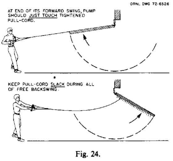
1. Gradually start the pump swinging back and forth, moving your arms and body as illustrated and pulling mostly with your legs and body.
2. Stand at such a distance from the pump that you can pull the pump toward you until the forward- swinging pump just touches the tightly stretched pull-cord and at such a distance that you can keep the pull-cord slack during the whole of the pump's free backswing.
3. To be sure you do not reduce the amount of air pumped, rapidly move your arms forward as soon as the forward-swinging pump touches the tightened pull-cord. Hold your arms forward until the pump again starts to swing toward you.
IX. SOLUTIONS TO SPECIAL PROBLEMS
A. Increasing the Usefulness of Shelters by Supplying 40 cfm per Planned Occupant
If a shelter is fully occupied for days during hot weather and is cooled both day and night by pumping through it and distributing at least 40 cubic feet per minute of outdoor air for each occupant more than is required to maintain tolerable temperatures at night these advantages result:
° The shelter occupants will be exposed to effective temperatures less than 2oF higher than the current effective temperatures outdoors, and at night will get relief from extreme heat.
° The floors, walls, etc. of a shelter so ventilated will be cooled at night to temperatures well below daytime temperatures. Therefore, during the day a considerable fraction of the occupants' body heat will flow into the floors, walls, and other parts of the shelter and less body heat will have to be carried out by the exhaust air during the hottest hours of the day. Thus daytime temperatures will be reduced.
° Since the shelter occupants will be cooler and will sweat less, especially at night, they will need less water than they would require if the shelter were ventilated at a rate of less than 40 cfm per occupant. (If the outdoor air is very hot and desert-dry, it usually is better to supply less than 40 cfm per occupant during the hottest hours of the day.)
° If the shelter were to be endangered by the entry of outside smoke, carbon monoxide or other poisonous gases, or heavy descending fallout under windy conditions, ventilation of the shelter could be temporarily restricted or stopped for a longer period than would be practical if the shelter itself were warmer at the beginning of such a crisis period.
Book Page: 209
° The shelter could be occupied beyond its rated capacity without problems caused by overcrowding becoming as serious as would be the case if smaller- capacity air pumps were to be installed and used.
B. Pre-Cooling Shelters
If the shelter itself is cooler than the occupants, more of the body heat of occupants can flow into its cool walls, ceiling, and floor. Therefore, it would be advantageous to pre-cool a shelter that may soon be occupied, especially during hot weather. KAPs (or other air pumps or fans) can be used to pre-cool a shelter by forcing the maximum volume of cooling outdoor air through the shelter and by distributing it within the shelter. A shelter should be pre-cooled at all times when the air temperature outdoors is lower than the air temperature inside the shelter. Then, if the pre-cooled shelter is used, the occupants will be kept cooler at a given rate of ventilation than if the shelter had not been pre-cooled, because the air will not have to carry all of their body heat out of the shelter.
C. Increasing the Effectiveness of a KAP
If you want to increase the volume of air that a KAP with good metal hinges can force through a shelter, install side baffles (see Fig. 25). Side baffles should be rigidly fixed to form two stationary "walls," one on each side of the swinging pump frame. They can be made of plywood, boards, doors, table tops, or even well-braced plastic. A space or clearance of 1/2 to 1 in. should be maintained between the inner side of each baffle and the outer side of the swinging frame.
By installing side baffles you may be able to increase the volume of air your KAP will pump by as much as 20%, if it is in good repair and the openings around it are small.
Fig. 25. Side baffles. ORNL-DWG 66-12334R 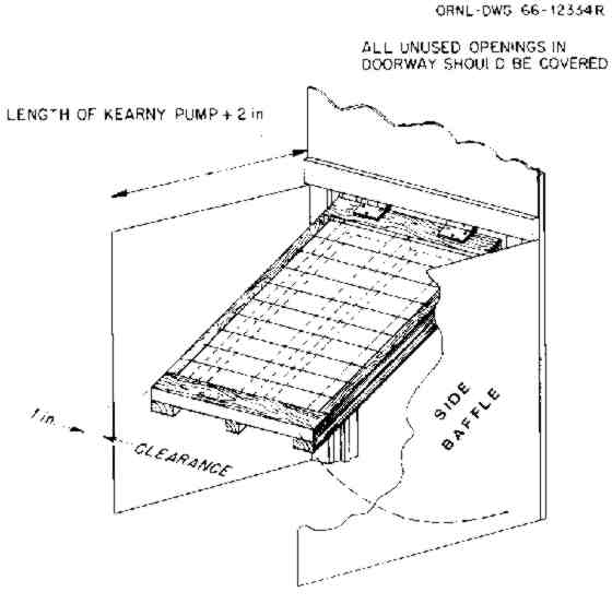
D. Operating a KAP as an Exhaust Pump
In some shelters, a KAP can be operated most effectively by using it as an exhaust pump. This can be done by pushing it with a push-pole attached to its center vertical brace. Push-pole operation is sometimes the best way to suck" outdoor air into a shelter by pumping air out of the shelter in the natural direction of air flow; for example, up an elevator shaft or up a stairwell. This method is especially useful in those basement shelters in which air-intake openings are impractical for installing KAPs. This would be the case if the air-intake openings are small, exposed windows or holes broken in the ceiling of a shelter in a building.
To pump a large KAP most effectively with a push-pole, stand with your back to the KAP and grasp the push-pole with both hands. Using mostly your leg muscles, push the KAP by pulling the free end of its push-pole toward you.
Book Page: 210
Figure 26 shows an improvised, flexible connection of a push-pole attached to the center brace of a large KAP 28 in. from the top of its frame.
Fig. 26. Push-pole flexible connection. ORNL DWG 66-12332R 
E. Ventilating a Shelter with Only One Opening
Some basement rooms that may be used as shelters have only one opening, the doorway. A KAP can be used to ventilate such a shelter room if enough well-mixed and distributed air is moving just outside the doorway, or if air from outdoors can be pumped in by another KAP and made to flow in a hallway or room and pass just outside this doorway. Figure 27 indicates how to ventilate such a one-opening room by operating a 3-ft KAP as an air-intake pump in the upper part of the doorway.
Below such a doorway KAP, a "divider" 6 ft to 8 ft long can be installed. The divider permits exhaust air to flow out of the room without much of it being "sucked" back into the room by the KAP swinging above it. Plywood, reinforced heavy cardboard, or even well-braced plastic can be used to make a divider. It should be installed so that, in a possible emergency, it can be jerked out of the way in a few seconds.
When used with a divider, a 36 X 29 in. KAP can pump almost 1000 cubic feet of air per minute into and out of such a shelter room. Although 1000 cubic feet of well distributed air is sufficient for several times as many as 25 shelter occupants under most temperate climate conditions, it is enough for only about 25 people in a one-entry room under exceptionally severe heat-wave conditions. Furthermore, to make it habitable for even 25 people under such conditions, the air in this room must be kept from rising more than 20 F above the temperature outdoors. This can be done using a second air-supply KAP to pump enough outdoor air through the building and in some cases also using air-distribution KAPs in spaces outside the one-entry room. The KAP in the doorway of a one-entry room should supply 40 cfm per occupant of this room.
In order to prevent any of the used, warmed, exhaust air from the one-entry room from being "sucked" by the doorway KAP back into the room, a stiffened rectangular duct can be built so as to extend the exhaust-opening (in the lower part of the doorway) several feet outside the room. Such a duct can be built of plastic supported by a frame of small boards. It can be used to discharge the exhaust air far enough away from the KAP and downstream in the airflow outside the one-opening room so that no exhausted air can be "sucked" back into the room.
Book Page: 211
Fig. 27. Use of a "divider" to ventilate a shelter with only one opening.
ORNL DWG 75-8203 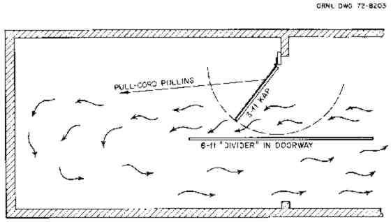
F. Installing a KAP in a Steel-Framed Doorway
If you need to install a KAP in a steel-framed doorway and it is not feasible to screw or otherwise permanently connect it to the doorway, you can attach the KAP by using a few boards and some cord, as illustrated by Figs. 28 and 29. The two horizontal boards shown extending across the doorway are squeezed tightly against the two sides of the wall in which the doorway is located by tightening two loops of cord, one near each side of the doorway. One loop is illustrated. A cord is first tightened around the two horizontal boards. Then the looped cord is further tightened by binding it in the center with another cord, as illustrated.
Two large "C" clamps serve even better than two looped cords. However, secure support for a swinging KAP still requires the use of a vertical support board on each side of the doorway, as illustrated.
Fig. 28. STEEL DOOR FRAME. ORNL DWG 72-6564 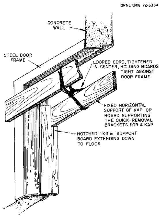
Book Page: 212
Figure 29 shows a quick-removal bracket supported by two horizontal boards tightened across the upper part of a doorway by looped cords, as described above. Also, study Fig. 19 and its accompanying instructions.
Fig. 29. (Quick Removal Bracket on Doorway) ORNL DWG 72-6617 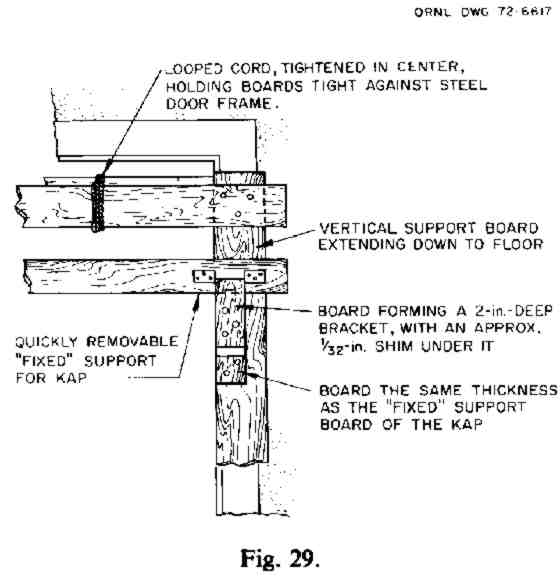
G. Building More Durable KAPs
If you are building KAPs in normal times, you may want to use materials that will make your pumps last longer, even though these materials are more difficult to obtain and are more expensive.
Durability tests have shown that the KAP parts that wear out first are the flaps and the pulleys. In 6-ft KAPs. the lower flaps are subject to hard use. Lower flaps made of 6-oz (per sq. yd), clear, nylon- reinforced, plied vinyl have lasted undamaged for over 1000 hours of full-stroke pumping, without having their edges reinforced. Lower flaps made of 6- mil nylon-reinforced polyethylene, without edge reinforcements, have lasted for 1000 hours with only minor damage.
The best pulley tested was a marine pulley such as that used on small sailboats, with a Delrin (DuPont) 2-in.-diameter wheel and 3/16-in. stainless steel shaft. This pulley was undamaged after operating a 6-ft KAP for 324 hours. The pulley appeared to be good for hundreds of hours of further operation.
The best pulley-cords tested were of braided dacron or nylon.
H. Using Air Filters
To supply shelter occupants with filtered air usually would be of much less importance to their survival and health than to provide them with adequate volumes of outdoor air to maintain tolerable temperatures. However. filtering the entering air could prove worthwhile, provided:
° Your shelter is not in an area likely to be subjected to blast, or it is a blast shelter with blast doors and blast valves protecting everything inside.
° Work on filters is started after you have completed more essential work, including the building of a high-protection-factor shelter, making, installing, and testing the necessary number of KAPs, storing adequate water, making a homemade fallout meter, etc.
° You have enough low-resistance filters (such as fiberglass dust filters used in furnaces and air- conditioners) and other materials for building the necessary large, supported filter in front of your KAP.
° Your KAP can pump an adequate volume of air through the filter and shelter.
° The filter is installed so that it can be easily removed if shelter temperatures rise too high.
To prevent a filter used with a KAP from causing too great a reduction in the volume of air that the KAP can pump through your shelter, you must use large areas of low-resistance filter material. An example: In one ventilation test, a large basement shelter was used which had two ordinary doorways at its opposite ends. These served as its air-intake and its air-exhaust openings. A 72 X 29 in. KAP operating in one doorway pumped almost 5000 cubic feet per minute through the shelter. But when a filter frame holding 26 square feet of l-in.-thick fiberglass dust filters was placed across the air-intake stairwell, the KAP could pump only about 3400 cfm through this filter and the shelter.
Book Page: 213
| MENU: HOME » SURVIVAL » Index of States |